Programmable Logic Simulator
The beauty of the i-TRiLOGI is that you can test run your program off-line directly on the same PC that runs i-TRiLOGI, or connect on-line to a real PLC located at some other parts of the world to access to all its real-time data. The experiences are almost identical to each other. They use the same visual feedback method about the logic states of I/O and internal data. You can test run the i-TRiLOGI program offline thanks to its built-in simulator engine which is in effect a "soft PLC" that executes all the commands that the actual "hard" PLC understands.
The simulator screen and the view variable screens are shared by both the simulator and the on-line monitoring mode and will be described in this document.
1. Run Simulation
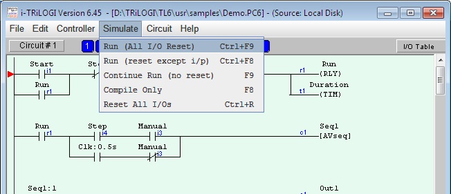
All i-TRiLOGI programs can be almost fully simulated on your PC. You invoke the Simulator by clicking on the "Simulate" Menu and select one of the three Run options:
Run (All I/O Reset) - Clear all inputs, outputs, relays, timers and counter bits to logic OFF, clear all internal memory variables to zero and all strings to empty string before running the simulator..
Run (reset except i/p) - The same as the above, but the input logic state will be kept. This is useful if you have simulated the program halfway and then close the simulator. You may wish to maintain the input logic states of the control scenario while resetting the rest of the simulator's data.
Continue Run (no reset) - allows you to continue a previously aborted simulation session..
2. The Simulator Screen
When you run the simulator, i-TRiLOGI will immediately compile the ladder program and if no error is detected, it will instantly proceed to open up the "Programmable Logic Simulator" screen, as shown below:
The simulator screen comprises 5 columns: Input, Timer, Counter/Sequencer, Relay, and Output. With the exception of the Relay table which contains up to 512 elements and the timer table which contain up to 128 elements, all other columns contain 256 elements each and has a vertical scroll bar. You can use the mouse to scroll each column independently to locate the desired I/O.
The label names for the inputs, outputs, relays, timers and counters defined earlier in the I/O tables automatically appear in their respective columns. To the left of each label name column is an "LED" lamp column which indicates the ON/OFF state of the respective I/O.. A red color lamp represents the ON state of an I/O, whereas a dark grey color lamp represents an OFF state. The I/O number is indicated in the middle of the lamp.
The simulator requires the use of the mouse to work properly so it is important to remember the mouse button actions as follow:
Left Mouse Button Turn ON the I/O when pressed.
Turn OFF when button is released.Right Mouse Button Toggle the I/O when pressed once.
(i.e. OFF becomes ON and ON become OFF)
There is a check box with the name "Control" near the upper right hand corner of the simulator. This check box must be "checked" before you can force set/reset the I/O within the simulator. When running the simulator this box is normally checked. But when you run the "Full Screen Monitoring", this box is normally unchecked to avoid acccidentally changing the state of a PLC's I/O.
3. View, Select, Pause, Reset Buttons
| View TBASIC Variables. See document on Viewing System Variables | |
| Halt the Simulator (including clock pulses) | |
| Reset all I/Os and data in the simulator engine.
(same as <Ctrl-F9>) (Press <Ctrl-F8> to reset all I/Os except the inputs) |
|
| Not available during Simulation. See "On-line Monitoring" for description of this button. |
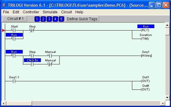
4. Displaying I/O Status on Ladder Diagram
The logic states of any I/O can be observed on the ladder diagram directly. An input, output, relay, timer or counter that is turned ON will have its label name highlighted in the ladder diagram. This feature helps greatly in debugging and understanding the logical relationship between each I/O. For example, from the above figure, we can see clearly how the "Self-latching" circuit for relay "Run" works. When we first turn ON the "Start" input, "Run" will be energized and its contact which is parallel to "Start" will hold itself in the ON state, even if we subsequently turn OFF the "Start" input.
Note that whether the highlight is turned is based strictly on the logic state of an element. You will have to interpret whether the contact is opened or closed by examining if it is a normally-open (N.O.) or a normally-closed (N.C.) contact. A highlighted N.C. contact means that the contact is opened, whereas a highlighted N.O. contact means that the contact is closed.
At any time you can reset all the I/Os so that they will not appear highlighted in the ladder program by pressing <Ctrl-R>.
5. Simulating the COM Ports
A. Simulating Incomming Data With INPUT$(ch)
It is possible to test the INPUT$(ch) command with the i-TRiLOGI Simulator. Whenever an INPUT$(ch) command is executed during a simulation, a new window will pop up that allows you to enter a string for the INPUT$(ch) command to accept.
For Example: If the following code is executed during simulation:
A$ = INPUT$(1)
Then a window will pop up for you to enter a string to be sent to Com port 1, since channel 1 (RS232) was used in the above code (you may want to enter something that could be received during normal PLC operation)
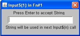
Then if you entered the string "This is a simulation of Com port 1", you would see the following string in A$ in the view variables - Strings window:
![]()
B. Simulating Outgoing Data With PRINT
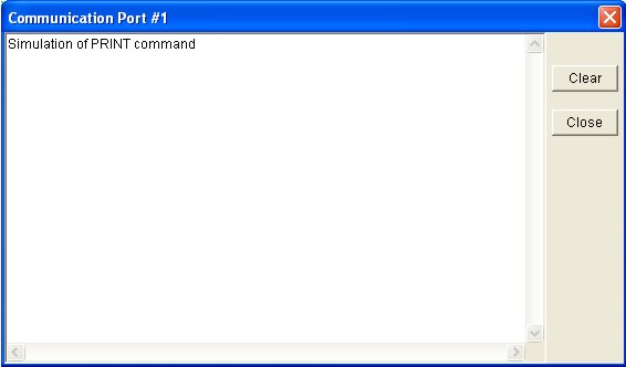
It is possible to test the PRINT #ch command with the i-TRiLOGI Simulator. Whenever a PRINT #ch command is executed during a simulation, a new window will pop up that displays any data that was printed using the PRINT #ch command.
For Example: If the following code is executed during simulation:
PRINT #1 "Simulation of PRINT command"
Then a window will pop up for you that displays the data to be sent out of Com port 1, since channel 1 (RS232) was used in the above code (you may want to enter something that could be sent during normal PLC operation)
NOTE:
i-TRiLOGI version 6.2 and up now includes a ![]() button to clear
data in the window shown above.
button to clear
data in the window shown above.
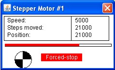
6. Simulating the Stepper Motor
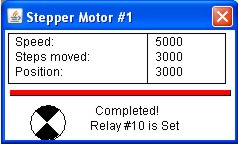
It is possible to test the Stepper Motor functions with the simulator. Once you have set the speed on a particular stepper motor channel using the STEPSPEED command, you can simulate the STEPMOVE, STEPMOVEABS, STEPHOME, AND STEPSTOP functions.
For Example: The motor speed could be set to 5000 pulses per second using the following code:
STEPSPEED 1,5000,100 ' 5000 pps, 100 steps to reach full speed
Then, if the following command to move the stepper motor was initiated, a stepper motor simulation window would pop as shown below.
STEPMOVE 1,3000,10 ' Move stepper motor on channel 1 by 3000 steps in the forward direction and turn on relay #10 at the end
You can also simulate the STEPMOVEABS command and the simulator will keep track of the stepper motors position for each channel, just like the PLCs stepper motor controller, using the STEPHOME command as a postition reference.
NEW! : F-Series PLC users have to option of using the PLC as a stepper motor driver to directly drive a stepper motor on each channel instead of just sending the control pulse and direction signal to an external driver. It is now possible to simulate the stepper motor driver as well, in both full step mode and half step mode. The simulator will not differentiate between a stepper motor driver command and a stepper motor controller command but it will accept either.
The simulator will also reconize a STEPSTOP command. If the following code were executed during simulation after a STEPMOVE command, then the simulator would react as shown below:
STEPSTOP 1 ' Stop motion on stepper motor channel 1