ch = channel number (1-16)
Err = Closed-loop Error
(i.e. Set point value - Feedback Value)
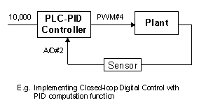
The controller may obtain feedback from ADC, High Speed Counters, PULSEFREQUENCY or other means. The obtained result is then scaled and subtracted from the desired (set point) value to get "Err ". All computations are performed in 32-bit integers and the function returns a 32-bit integer which can be assigned to any variable. Any scaling for actual output (DAC or PWM) will be computed by the user within the same CusFn and sent to the output.

E = 10000 - ADC(2)*20
A = PIDcompute(5,E)
setPWM 4, (A + 8000)/100
The desired output (stored in variable A) is then added to the offset value 8000 and then scaled down by a factor of 100 before being sent out physically via PWM Channel #4.
Important: In actual implementation, use a clock pulse such as 0.1s, 0.5s or 1s etc to periodically activate the PIDcompute( ) function so that digital control in discrete-time can be implemented. The PID sampling period depends on the time constant of the system. For very slow response processes such as the cooking temperature of a large body of water, the time constant is very large and even slower than 1.0 seconds clock may be sufficient. Do not use unnecessarily short sampling time because it increases computation time and slows down overall performance of the system.