| Available since version 6.43, this new Analog calibration
tool allows OEMs to perform quick calibration of the PLC's analog inputs and
outputs. This new tool is normally located under the "Controller" Menu,
Alternatively, this tool may also be opened from the "Ethernet & ADC
Configuration Tool -> Advanced Config." by clicking on the button labelled
"Auto-Calibrate Analog".
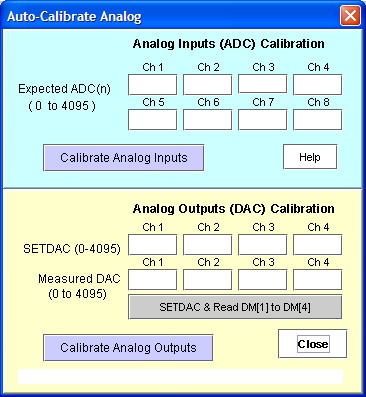
The Auto Calibrate Analog I/O screen is split into two parts. The upper portion is
meant for calibration of the Analog inputs. The lower portion is for calibration of the
PLC's analog outputs. We will explain each part separately in the next few sections as you
may only need to calibrate what you need to use.
However, for those not too familiar with how to communicate with the PLC via i-TRiLOGI,
a short section is also included below that describes
the connection procedure. |
 |
In order to calibrate the analog inputs, you need to have one or more stable and quiet
reference voltage source(s) and a precision voltmeter. First, connect the voltage source
to all the PLC's analog inputs that you wish to calibrate. For best precision, select a
voltage source that falls somewhere in the middle of the range of analog values that you
are concerned with. For example, if the temperature sensor that you normally measure with
would return a voltage between 2.3V and 4.5V. Then it is best to calibrate using a voltage
source around 3V. After connecting the voltage source to the analog inputs, use your
precision voltmeter to measure the actual voltage and convert it to a reading that you
expect the ADC(n) to return.
E.g. if your voltage source measures 3.045V and your analog input range is 0-5V, then
the expected reading that ADC(n) should return corresponding to 3.045V should be =
3.045/5.000 x 4096 = 2494. Lets say If you are only calibrating analog input #1, #3 , #7
and #8 only and the rest are not used, then enter the value into the "Expected
ADC(n)" fields for each channel as shown below. Leave any unused channel blank.
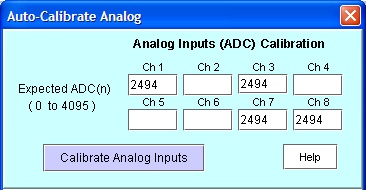
When you have finished entering the expected ADC data, then click on the button
"Calibrate Analog Inputs" to start calibration.
The calibration program will first clear the old calibration data in the PLC and reboot
it once. After that it will read 50 samples from the PLC's analog inputs and compare it
against the expected ADC(n) value. The average readings of the 50 samples is then used to
compute the calibration parameters and the program will store the calibration parameters
into the PLC and reboot it again. The analog inputs are thus completed in a single step.
You may also use different voltage references to calibrate different analog channels.
Simply leave the channel(s) that you do not want to calibrate with the currently selected
voltage source BLANK. (Note: The calibration tool will NOT
calibrate any channels whose field are left blank):
In order to calibrate an analog output, you need to set the DAC to a certain value and
then use a measuring instrument to measure the resulting output voltage (or current,
if an AN20MA-2 interface board is used). The difference between the expected DAC
output and measured DAC output is used to compute the calibration parameters for the PLC's
analog output.
For example, if you wish to calibrate analog output #1 and #2 and using an analog
output value of 2048, you first must clear the old analog calibration paramters (using the
Ethernet & ADC Configuration Tool
-> Advanced Config), then write a program into your PLC to execute the following
two statements:
SETDAC 1, 2048
SETDAC 2, 2048
Your PLC will then output an uncalibrated analog output voltage on the DAC which you
can then measure with a precision voltmeter. If your analog outputs are configured for the
0 to 5V range, then ideally at 2048 you expect the DAC to output a voltage =
2048/4096*5.000 = 2.500V.
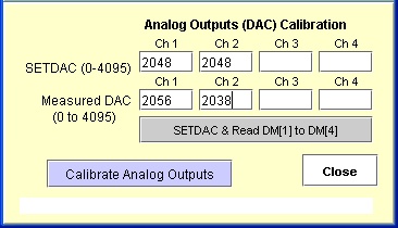
However, assuming that your precision volmeter measures a voltage of 2.510V at DAC #1
and 2.488V at DAC #2. This means the You will then need to convert the two measured
readings to the range of 0-4096 and then enter into the "Measured DAC" fields.
For DAC #1, the measured reading = 2.510/5 x 4096 = 2056 and for DAC #2, the measured
reading = 2.488/5 x 4096 = 2038. Enter these two values into the table as
shown in the above diagram.
After you have entered all the above parameters, you can then click on the
"Calibrate Analog Outputs" button to start calibration of the analog outputs.
The program will compute the calibration parameters based on the "SETDAC" and
the "Measured DAC", write them into the PLC and then reboot it to complete the
calibration.
The procedure described in the last section may be a little bit tedious to work with
since it involves several manual steps and require measuring the analog output readings
and convert them into the 0-4096 range. It however illustrates the principle used by the
calibration routine.
In order to automate the calibration of the analog outputs, an additional button  is included to assist with the task.
When you click on this button, i-TRiLOGI will perform the following tasks:
1) It clears all the old analog output calibration parameters for any analog output
channel that has a non-blank entry into the SETDAC field.
2) It reboots the PLC so that the analog output from the PLC will be freed from any old
calibration data.
2) It sets the corresponding analog output channel using the data entered into the
"SETDAC" field.
3) It waits for one second and then read the DM[1] to DM[4] data from the PLC and store
into the "Measured DAC" fields for DAC #1 to #4.
Therefore, if your PLC's analog inputs are already calibrated previously, you can make
use of your calibrated Analog inputs to measure your uncalibrated analog outputs and store
the measured readings into DM[1] to DM[4] to be used by your calibration program!
What you do is to connect the PLC's DAC #1 to its own ADC #1, DAC #2 to ADC #2 etc, and
then write a PLC program to read the ADC data, take an average readings to even out white
noise, then write the average readings into DM[1] to DM[4]. The button can then retrieve the measured DAC readings from the DM[1] and
DM[2] in a single step to perform the calibration.
Alternatively, if you have a precision measuring instrument that is capable of talking
to your PLC (e.g. another PLC or an instrument that can communicate with the PLC via
Modbus protocol), then the precision instrument can measure the DAC output of the PLC and
write the measured readings into the DM[1] to DM[4] of the PLC, which can also be used by
the button to read the measured readings
easily.
Once the reading has been obtained, just click on the  to complete
the calibration.
to complete
the calibration.
We have therefore reduce the analog output calibration to a simple two-step process
which can be easily handled by any production operator during production of an OEM
equipment.
This program communicates with the PLC via the same user interface as all
other communication functions under the "Controller" menu. This means that the
calibration tool will be communicating with the PLC using the TCP/IP protocol. If the PLC
has a built-in Ethernet port then it should be connected to an Ethernet router or switch
with a preconfigured private static IP address. If the PC is also on the same network then
you simply login to the PLC server using the private IP address of the PLC.
However, if you do not know or have lost the IP address of the PLC, then it is still
possible to calibrate the PLC's by connecting the serial ports on the PLC to the PC.
In this case, you will need to run the TLServer on your PC and configure the PC's serial port to work with
the PLC's serial port. The configuration tool will connect to the PLC indirectly via
the TLServer software. Click
here for more details about TLServer.
If your i-TRiLOGI is not yet connected to a TLServer software or directly to the PLC
built-in hostlink command server (known as F-Server in the Nano, FMD or F-series PLCs),
then when you try to calibrate the PLC you will see the login popup windows as follow:
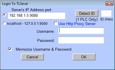
If you are connecting to the PLC via TLServer that runs on the same PC as i-TRiLOGI,
then simply select the "localhost-127.0.0.1:9080" to connect to TLServer.
If you are connecting to the PLC's F-server, the IP address of the PLCs' and the port
number should be entered in the "Server's IP Address:Port" field and select the
corresponding radio button. The default settings for the Ethernet port are IP: 192.168.1.5
and port: 9080 with no username and password required (same as shown in the screenshot
above). Once you have entered the correct login information, click on the "Detect
ID" button and wait for the PLCs ID to populate in ID box (01 is the default ID).
Then click "OK" and you are now connected to the PLC for any calibration work.