 Note: Default settings shown
here.
Note: Default settings shown
here.
Ethernet & ADC Configuration Tool
This tool, which is located in the "Controller" Menu, allows you to configure
the Ethernet Port and ADC/RTC calibration settings on a TRi's PLC with built-in Ethernet
port (Nano-10, FMD Series, Fx-Series, and EZWire PLCs). When the “Ethernet & ADC Calibration” is
selected, you will see the following screen:
The configuration tool communicates with the PLC via the same user interface as all other communication functions under the "Controller" menu. This means that the configuration tool will be communicating with the PLC using TCP/IP protocol. Since only PLCs with built-in Ethernet can utilize this function, it means that most likely the PLC would be connected to a router or switch with a preconfigured static IP address. If your PC is also on the same network then you simply login to the PLC server using the static IP address of the PLC. Of course if the PLC's Ethernet port is already mapped to a public IP address then you can also remotely configure the PLC via the Internet.
However, if you do not know or have lost the IP address of the PLC, then it is still possible to configure the PLC's ethernet port by connecting the serial ports on the PLC to the PC. However, in this case you will need to run the TLServer on your PC and configure the serial port to work with the PLC's serial port. The configuration tool will connect to the PLC indirectly via the TLServer software. Click here for more details about TLServer.
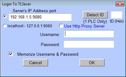
Before you make any changes to the PLC's Ethernet configuration parameters, it is a good idea to retrieve the current settings. You can do this by clicking on the “Retrieve Parameters from PLC” button and answer "Yes" when prompted. If your i-TRiLOGI is not yet connected to a TLServer software or directly to the PLC built-in hostlink command server (known as F-Server in the F-series PLCs), then you will see the login popup windows as follow:
If you are connecting to the PLC via TLServer that runs on the same PC as i-TRiLOGI, then simply select the "localhost-127.0.0.1:9080" to connect to TLServer.
If you are connecting to the PLC's host link command server, the IP address of the PLCs' and the port number should be entered in the "Server's IP Address:Port" field and select the corresponding radio button. The default settings for the Ethernet port are IP: 192.168.1.5 and port: 9080 with no username and password required (same as shown in the screenshot above). Once you have entered the correct login information, click on the "Detect ID" button and wait for the PLCs ID to populate in ID box (01 is the default ID). Then click "OK" and the configuraton tool will be populated with the current Ethernet settings.
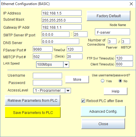
After you have retrieved the existing parameters from the PLC, you will see that various fields in the configuration software screen are filled up. These fields and the remaining unpopulated fields can be configured as described in the rest of this document.
BASIC CONFIGURATION
IP Address
![]()
One of the most important parameters that you must define here is the “IP Address” field (as shown above). By default, every F-series PLC is shipped with the static IP address: “192.168.1.5”. You will need to assign the PLC’s with an IP address that is unique on your network and yet is accessible from your PC. If you are on a company network, then you must consult your company’s system administrator to assign you a useable IP address.
However, if your PC is connected to a small local area network, then most likely you will have a LAN IP address of 192.168.XXX.YYY. For proper networking, you should set the PLC’s IP address to “192.168.XXX.ZZZ”. i.e. The first three numbers should match each other. The fourth number (ZZZ) should be an IP address that is not used by any other devices on your network.
Note that majority of small LANs are built using a network router that assigns dynamic IP addresses (called DHCP server) to the PC. You should enter the administrator page of the router and define the range of DHCP for use by the PCs and then you may assign the PLC with any IP address that is outside of the DHCP range. E.g. If you define the DHCP address range to be 192.168.1.100 to 192.168.1.150, then you may assign the PLC with any IP address between 192.168.1.2 to 192.168.99 (Usually the router itself would have the IP address 192.168.1.1, and the address 192.168.1.255 is reserved so these two addresses are not available) and also between 192.168.151 to 192.168.1.254 (again making sure that 192.168.1.254 is not already used by your router).
GateWay IP Addr
![]()
The Gateway IP address (as shown above) lets the F-series PLC communicate with other LAN segments or connect to the Internet. The gateway address is usually the local IP address of the router where the PLC is connected. For small local networks with no plan for connection to the Internet, the Gateway IP Address is not needed and can be set to 0.0.0.0. But if you plan to use the Fserver’s email capability then you must fill in the correct Gateway IP Address. Ask your system administrator if you have any question about this.
SMTP Server IP:port
![]()
The SMTP (Simple Mail Transport Protocol) Server field (as shown above) lets you define the IP address and port # of the email server that the PLC can use to send out emails from user’s program (for Super PLC users, please refer to Chapter 2.4.3 of the User Manual for more details on how to program the PLC to send emails).
If you are configuring the PLC to us TLServer as an Email Server Relay, then you would use the IP address of the PC running TLServer as the SMTP Server IP address. The port number should be what you have configured in
TLServer-->Setup Emails-->Port # to Relay PLC Email
If you are not using the Email Server Relay feature, you would configure the same SMTP server that your normal email client software such as Thunderbird or MS Outlook uses to send out email. You can ask your Internet Service Provider (ISP) for the IP address of their SMTP server. The ISP usually provides the SMTP server in domain name form (such as “mail.sbcglobal.net”), but you should also be able to request the numerical IP address of the SMTP server from the ISP.
For Windows XP or Vista users, you can resolve the IP address as follows: First, launch the “Command Prompt” window. Then enter the command nslookup <smtpserver name>” to get the IP address. An example is shown below where the IP address of mail.sbcglobal.net is resolved to the IP address: “207.115.36.120”:
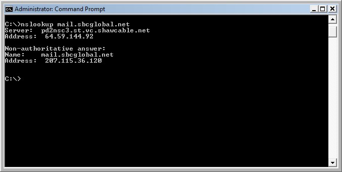
Windows users may also search the Internet for a free “host.exe” tool that lets you resolve the IP address from a given domain name (one host.exe tool that we found to work was downloaded from http://pigtail.net/LRP/dig/). For example, executing the command line: “host mail.sbcglobal.net” will resolve its IP address. (Of course you can only use this smtp server provided your ISP is SBC, almost no SMTP server will relay emails from a client that is not one of its own subscribers).
If you do not plan to use the FServer to send out emails yet, then you can leave the default SMTP Server IP Address = 0.0.0.0. You can change the settings anytime later when you need it.
DNS Server IP Address
![]()
DNS (Domain Name Server) allows the FServer to contact a remote location by means of domain name instead of IP Address. The DNS takes in the given domain name (such as yahoo.com) and returns the IP address of the target server. You only need to fill in the DNS IP Address if you are asking the FServer to contact a remote server by domain name, instead of by IP Address. However, currently this feature is not supported on the FServer and hence it may be left as the default value of 0.0.0.0.
No. of Connections (FServer/ Modbus TCP)
![]()
The F-series CPU assigns sufficient memory to support up to a maximum of 10 simultaneous TCP/IP connections to the FServer and Modbus/TCP server. By default, the Fserver is assigned a maximum of 7 connections (even if 3 is shown) and the MBTCP server is assigned 3 connections. However, to improve flexibility, you can re-assign the mix of maximum connections between the two servers as long as the no. of Modbus/TCP connections does not exceed 5 and the no. of FServer connections does not exceed 7. This means that you can define 5 to 7 FServer connections and 3 to 5 Modbus/TCP connections. When you change the number in one box the other box will change automatically so that the total number of possible connections remains at 10.
FServer Port No.
![]()
The Port number is a 16-bit integer (range 0 to 65535) that needs to be specified on top of the IP address when accessing the FServer from across the network. The default value is 9080, which is the same default value used by the TLServer and i-TRiLOGI client software. Please see the i-TRiLOGI programmer’s manual for an explanation of the use of the port number. One reason why you may want to change the port number is to use the “port forwarding” capability of an NAT router so that different F-series PLCs may be accessible from the Internet using the same public IP address of the router but with different port numbers.
Modbus/TCP Secondary Port No.
![]()
According to MODBUS.ORG specifications, all Modbus/TCP servers must listen on port #502. However, Modbus.org also permits the device to be assigned a different secondary port number. As such, the Modbus/TCP server will always listen on port #502 for all of its connections by default. Should you choose to define a secondary port number, then the Modbus/TCP server will only listen on port 502 on one connection while the additional connections (1 to a maximum of 4) would be listening on the secondary port. You may specify any port number between 1024 and 65535 (except for the port number already used by the FServer) to be the secondary port number. Please see the i-TRiLOGI programmer’s manual for an explanation of the use of the port number. One reason why you may want to change the port number is to use the “port forwarding” capability of an NAT router so that different F-series PLCs may be accessible from the Internet using the same public IP address of the router but with different port numbers.
Lan Speed
![]()
You can set the LAN speed of Super PLCs to be either 10 Mbps or 100 Mbps (default) per second using this menu option. Most modern Ethernet switch or router will automatically connect to the PLC using its default LAN speed and there is usually no need for user to configure this option except in very special application where the devices are connected via a 10Mbps Ethernet "hub", which demands all connected device to be set to the same 10Mbps LAN speed.
Node Name
![]()
You can assign up to 16 ASCII characters (any character) in naming a PLC. The node name is currently not used by the network router so it is merely a convenient name for user to identify a PLC.
FTP Server Timeout
Configure the number of seconds the PLCs FTP server will keep a FTP client connection (ie. FileZilla) open while there is no activity. The default is 120s.
Client TImeout(s)
Configure the number of seconds the PLCs TCP client connection manager will keep a client connection (ie. initiated by the MBTCPCONNECT tag) open while there is no activity. The default is 600s (10 minutes). The minimum value is 5s and the maximum value is 6000s. It is recommend to leave this at the default value unless there is a specific reason to change it.
Username and Password (FServer only)
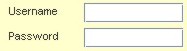
You can use the username and password feature to prevent unauthorized access to the FServer. It adopts the same proprietary encryption scheme used in the TLServer and i-TRiLOGI software to encrypt the password transmission. However, unlike the TLServer that allows you to define unlimited number of usernames and passwords, the FServer only permits a single username and password and this is limited to a length of 16 characters.
Use Username/Password (Yes/No)?
![]()
In applications where there is no danger of unauthorized access to the PLC via FServer, you can elect not to use the username/password. With the “No” option selected, the i-TRiLOGI client or Java Applet can log-in to the FServer using whatever username and password since FServer will bypass the username and password authentication and allow the client to log in.
Access Level
![]()
You can define the access level that the i-TRiLOGI client is permitted to operate under on the PLC. Three access levels are currently defined: 1 for Programmer, 2 for User and 3 for Guest. Please see the TLServer User Setup for the definition of the access levels.
Advanced Configuration
![]()
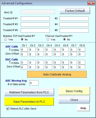
The Advanced Configuration button lets you configure other more advanced (beyond the basic Ethernet configuration), but less often used features of the PLC. This includes definition of the “Trusted IP” addresses as well as calibrations of the PLCs Analog I/Os and Real Time Clock (RTC).
ADVANCED CONFIGURATION
MAC ID
A Read Only field that contains 6 byte (48-bit) of Ethernet MAC ID.
Trusted IP - MODBUS/TCP Access Security
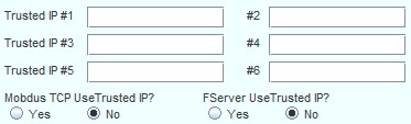
If an F-series PLC is to be accessible only on the local area network, then the direct connections offered by MODBUS/TCP provide simplicity without time-consuming login sequences. However, if the MODBUS/TCP port is to be exposed to the public Internet, then you ought to consider the security issues associated with MODBUS/TCP connections. Since a MODBUS/TCP connection does not require a username/password login sequence (unlike the FServer login), the only way to protect against unauthorized access is through the “Trusted IP” addresses defined using the F-Series Ethernet Configuration software.
The first thing you should do is to click on the “Retrieve Parameters from F-PLC” so that you can capture a copy of the current configuration in the PLC and you can then modify selectively. You can define a list of up to 6 “Trusted IP” addresses in this panel. To enable the Modbus/TCP Trusted IP, click on the “Yes” button next to the “Modbus/TCP Use Trusted IP”. Note: The FServer can also be enabled to only allow connections from devices that match one of the “Trusted IP” defined in this panel. This is on top of the username/password login sequence that can be enabled/disabled from the Basic Configuration screen. In other words, you can choose either security method to access the FServer or implement both security methods at the same time.
After you have defined the list of trusted IP addresses and checked the “Use Trusted IP” radio button, click on the “Save Parameters to FServer” to save your data to the PLC’s nonvolatile memory.
When “MODBUS/TCP Use Trusted IP” is enabled, it means that only TCP/IP packets that come from a client whose IP address matches one of the “Trusted IP” would be allowed connection to the MODBUS/TCP server.
Calibration of ADC and DAC & Moving Average Definition
The ADC and DAC are factory-calibrated such that a voltage of half of fullscale voltage (5.00V on F2424, and 10.00V on F1616-BA) should return a value of 2048 when read by the ADC(n) function. Likewise, an output voltage of half of fullscale voltage should be present at the DAC pin when you SETDAC to 2048. However, if there is a need to re-calibrate the ADC and DAC, you can follow the procedure outlined below.
Auto-Calibrate Analog
Please see the Auto-Analog I/Os Calibration Tool for instructions on utilizing the automatic ADC calibration feature.
Manual Analog Calibration
To perform calibration of an ADC channel, you need to supply a precise DC reference voltage to the ADC channel, and then check the analog readings obtained via the ADC(n) function and compare it to the expected value. If there is an error, you can apply a correction factor to it.
The bottom half of the "Advanced Configuration" screen contains ADC and DAC calibration constants that you can enter and transfer to the PLC, as shown below:
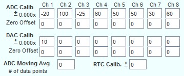
ADC Calib.
These fields are used to apply a multiplication factor to the value returned by ADC function. The multiplication factor = (1+ x/10000).
Example 1:
If you apply 2.500V to ADC #1 on a PLC with 5.000V full scale, you would expect the value returned by ADC(1) to be 2048. But the actual average reading centers around 2060.
Proportional Error = 2060/2048 = 1.005859
Multiplication factor required to correct this error = 1/1.005859 = 0.9942 = (1 – 58/10000) => x = -58
You should therefore enter a value of 58 into the “ADC Calib” field for Ch #1 and save it to the PLC. After the PLC has rebooted, the CPU would apply the multiplication factor of 0.9942 to the readings it received, which would correct the reading to: 2060 x 0.9942 = 2048.
Example 2:
If you apply 8.000V to ADC #8 on a PLC with 10.000V full scale, you would expect the ADC(8) function to return a value of 8.000/10.000 x 4096 = 3277. However, your program returned a value of 3230 from ADC(8).
Proportional Error = (3230)/3277 = 0.985658
Multiplication factor required to correct this error = 1/0.985658 = 1.0146 = (1+ 146/10000) => x = +146
To compensate for this error, enter a value of 146 in the “ADC Calib.” for Ch 8 and save it to the PLC. After the PLC has rebooted, the CPU would apply the multiplication factor of 1.0146 to the readings it received, which would correct the reading to: 3230 x 1.0146 = 3277.
Notes:
ADC Zero Offset
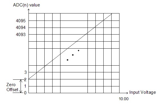
The zero offset error can be corrected by entering a value into the “ADC Zero Offset” field. Any number between –100 and 100 can be entered here. The ADC(n) function would add the zero-offset value that you entered here to the measured value and return the total sum to the calling routine.
DAC Calib.
A value x entered in each of these fields represents the multiplication factor (1 + x/10000) that the PLC will apply to the “value” parameter, which is executed by the command “SETDAC n, value” before actually writing to the DAC output. This allows the user to apply a correction factor to the DAC output if there is a problem with the DAC voltage.
Example 1:
If you execute “SETDAC 1,2048”, you would expect the DAC #1 to output 5.000V on a 10.000V full scale DAC, but instead you only get 4.960V.
Proportional Error = 4.960/5.000 = 0.992
Multiplication factor required to correct the DAC output = 1/0.992 = 1.0081 = (1+81/10000)
You can therefore enter the value “81” into the “DAC Calib.” field corresponding to DAC #1 and save the parameters to the PLC. After the PLC has rebooted, when you execute the statement “SETDAC 1,2048”, the CPU would apply the multiplication factor of 1.0081 to the actual digital value it sends to the DAC output. The actual DAC output =4.960V x 1.0081 = 5.000V.
Example 2: Same as Example 1 but you measure 5.030V when you expect 5.000V
Proportional Error = 5.030/5.000 = 1.006
Multiplication factor required to correct the DAC output = 1/1.006 = 0.9940 = (1 – 0.0060)
You should therefore enter the value –60 into the “DAC Calib” field corresponding to DAC #1 and save it to the PLC. After the PLC has rebooted, when you execute the statement “SETDAC 1,2048”, the PLC will apply the multiplication factor of 0.9940 to 2048 before it writes to the DAC hardware.
The actual DAC output = 5.030V x 0.994 = 5.000V
DAC Zero Offset
If you plot the line graph for the output voltage versus the DAC set value, the line should normally pass through the origin. But if there were any zero offset error, then the line would be above or below the origin.
The DAC output on the F-series PLC should not have any zero offset error and you normally should just leave these fields set to “0”.
However, if for any reason there is a need to apply a zero offset error correction, you can enter a value between –100 to +100 into the “DAC Zero Offset” field. The CPU would add the zero-offset value you enter into this field to the “X” in the “SETDAC n, x” statement and only send the sum to the actual DAC hardware.
A/D Moving Avg
![]()
This field lets you define the number of points of moving average that the F1616-BA CPU firmware uses to compute the value returned by the ADC(n) function (for F-series PLC users, please refer to Chapter 5.2.5 of the User Manual for an explanation of moving average).
A larger number of moving Average points has the positive effect of filtering out large noise spikes seen at the analog input, but the disadvantage is that the PLC would be slower in noticing a sudden step change at the analog input. If you specify a moving average of 1 point, that means no moving average will be used and the ADC(n) function will return the most recently sampled data at the analog input #n.