Show Posts

This section allows you to view all posts made by this member. Note that you can only see posts made in areas you currently have access to.


Messages - support

Pages: 1 ... 204 205 [206] 207 208 ... 212
3076
Technical support / Re: Communications problem
« on: September 01, 2003, 09:08:05 PM »
The COMM2 port on T100MX PLC does not support hostlink commands or MODBUS commands,  so you can't
use it for on-line monitoring etc. Only COMM1 and COMM3 can respond to host link or modbus commands. This is clearly mentioned in the PLC's installation guide.

COMM2 is mainly for use by TBASIC commands such as INPUT$, INCOMM, PRINT #, OUTCOMM and NETCMD$. It supports only up to 19,200 bps baud rate and the only format supported is 8 data bit, 1 stop bit and no parity.

3077
Technical support / Re: T100MD2424
« on: September 02, 2003, 12:45:17 PM »
Thanks for your kind remarks and vote of confidence in TRi?s products! It?s really great that there?s now a growing community of users who generously share their experiences in using TRi?s controllers in various projects. Thanks for contributing to the buzz.

3078
Technical support / Re: Connecting to a SCADA system
« on: September 03, 2003, 06:33:28 AM »
Which PLC model are you using? Only T100MD and T100MX support MODBUS on their COMM1 and COMM3 port. All you need to do is to define the baud rate on the SCADA program to the default value of 38,400, 8 data bit, 1 stop bit and no parity, no handshaking and define the device ID to be the same as what you have defined for the PLC (default is 01), then it should work transparently. Even if there is no program in the PLC the SCADA will be able to work with the PLC's using the MODBUS protocol. ?In fact, your PLC program should not write anything out of the serial port otherwise it will interfere with the SCADA polling of the PLC slave and results in no communication. Normally there is no need to change the PLC's baud rate (using SETBAUD) unless your SCADA is unable to use the PLC's default baud rate.

The easiest way to test the communication is to read from MODBUS register 40001 (binary address 0), which maps to input 1-16, then turn ON any of the first 16 inputs on the PLC and observe the changes to the value of 40001.

you are using the bit mapping instead of word mapping, please download the following updated document for the MODBUS mapping to the PLC's register:

http://www.tri-plc.com/appnotes/modbus-map.pdf

3079
Technical support / Re: Using VB6 to interrorgate Analog inputs
« on: September 04, 2003, 07:20:26 PM »
The M-series PLC does not automatically queries the ADC ports unless you program it specifically to do so. So in order read an ADC value from AD input #n, you need to execute the ADC(n) function periodically to retrieve the readings. That can be easily achieved using a clock pulse and execute the ADC(n) function periodicaly.

Once the ADC(n) function is executed, you can then use the "RVS0Bnn" command to read the ADC data from its internal registers. Alternatively, if you have read the values into DM
  • variable by executing e.g.


  DM[10] = ADC(1)

then you can use the host link command "RVDxxxx" to read the value from the DM.

We have a sample VB6 program that you can download from our website to assist you in writing your comm routine with work with the PLC, as follow:

http://www.tri-plc.com/applications/VBsample.htm


3080
Technical support / Re: Power supply for analog inputs
« on: September 06, 2003, 10:24:39 AM »
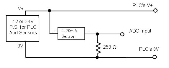
I think you are referring to the following wirings. Yes, it should work: ?


The picture show wiring of 1 sensor but it can be extended to all 8 sensors.

What kind of sensors are you using? $400 per module is pretty steep. If you are measuring thermocouple or microVolt signal you may like to check out the I-7018 which can connect directly to thermocouple. ?For more info on I-70xx, please visit:

http://www.tri-plc.com/i7000.htm


3081
Technical support / Re: Power supply for analog inputs
« on: August 29, 2003, 03:49:03 PM »
The T100MD888+ automatically uses the PLC's power supply to provide reference voltage and supply current to its analog i/o so there is no need to connect external power supply to the analog i/os.

I am not sure if your sensors has isolated power supply for the transmitter, or whether the "-" terminal of the two-wire transmitter is in common with its negative power rail. If it does then you can use the same power supply for the PLC as for the sensor transmitter.

If not, then you have to check for isolation issue. If you are using 4-20mA two-wire transmitter, then it needs to be connected to a 250 Ohm resistor to turn into 1 to 5V. The "-" terminal of the two wire-transmitter has to be connected to the PLC' 0V power rail. You need to check whether if this would create a short circuit on the transmitter circuitry. Use a meter to measure the voltage between the "-" terminal of the transmitter and its power supply to see if there is any active voltage. There should not be a constant DC voltage between them otherwise you will need to use a different power supply for the transmitter so that there will not be a ground fault.

3082
Technical support / Re: rtd
« on: September 10, 2003, 11:00:09 AM »
I assume you are using the RTD in series with a resistor to provide the voltage dividing effect as outlined in the document:

http://www.tri-plc.com/applications/PT100Interface.pdf

The only thing you need to check may be whether self-heating of the RTD may affect the readings slightly, but there should not be any long term ill effect on the connection.

3083
Technical support / Re: rtd (PT100 sensor)
« on: November 17, 2002, 07:23:07 AM »
The quickest means is to buy a commercial PT100 signal conditioner that will output 0-5V, 0-20mA or 0-20mA (the latter two can be converted into voltage by using a 250 ohm resistor) and connect to the T100MD888+'s analog input.

You can also build a two-resistor voltage divider using the PT100 as one of the resistors and construct a simple opAmp to amplify the voltage drop across the PT100 resistance into 0-5V.  A sample circuit can be found at the following link:

http://www.tri-plc.com/applications/PT100Interface.pdf


3084
Technical support / Re: Counter
« on: September 10, 2003, 11:11:08 AM »
Normal use of a down counter is by means of the output coil  -----(CTR) instead of [DNctr]. The latter is meant to be a ring counter which will roll over to the setvalue when it hits zero.

When a counter is reset, it is internally loaded with -1. That's how it is represented.

You can change the counter value anytime by assigning it with a new value in custom function:

 CTRPV[1] = 123   ' set the present value of the counter to 123.


3085
Technical support / Re: Trilogi under Linux
« on: September 10, 2003, 11:41:34 AM »
Unfortunately, the promise of Java being a "Write once, run everywhere" is still not a reality. We have tested the java program on red hat linux and face similar problem. Testing the java on other linux platform or different JVM version produce different set of problems. So in order to make the program works in most Linux platform there is too much re-development work to justify the expense since there is still only a very small number of users wanting to use linux with TRiLOGI.  

3086
Technical support / Re: LCD Current Limiting Resistor
« on: September 10, 2003, 11:06:37 AM »
The 150 ohm resistor is 5W in ratings. It is meant to be HOT! Anyway, if you can connect it in contact with some metal surface to help carry away the heat it is always appreciated! Otherwise, just good air flow will be sufficient.

3087
Technical support / Re: Multipoint host-link trouble
« on: September 10, 2003, 04:07:27 PM »
You can use either methods. Using WI is more straight forward (and the program will run quicker) but it affects 8 inputs in one command. If you only need one input the the rest of the inputs are not used then it does not matter.

3088
Technical support / Re: Multipoint host-link trouble
« on: September 09, 2003, 07:37:48 PM »
The PLC is refreshing all its physical input bit at every scan of the ladder logic even if the PLC program is halted. As such, when you write to the input register using the host link command "@01WIxxxxx", it will only change the input register temporarily,  and the PLC will on the next I/O scan change the input bits back to what it receive from the physical input.

The only inputs that you can change permenantly are those not controlled by the PLC. For the M-series PLC, the maximum inputs are 96, so above 96 you can change them. Since WI treat each channel as 8 bit, the input from 97 to 104 will occupy channel 12, or 0C hex. Try "@01WI0Cxxxxx*" and it should work on input #97 to 104 and so on.

3089
Technical support / Re: Wiring diagrams
« on: September 18, 2003, 10:52:24 AM »
COMM1 is just a RS232 port that uses only Tx, Rx and GND (2,3,5). You need to make a cable to connect to your MODBUS or OMRON slave. It is either:

2 - 2
3 - 3
5 - 5

or

2 - 3
3 - 2
5 - 5

The next thing to do is to use the SETBAUD function to set the baudrate of COMM1 to the same as your slave. (Alternatively, you can also set your slave's baud rate and communication to that of the PLC, which is by default 38,400, 8, 1, noparity.

To talk to a MODBUS slave, use the READMODBUS (11, x,x) or WRITEMODBUS ?11, x, x, x

To talk to OMRON slave, use the NETCMD$.

Please read the documentation on how to use the NETCMD$, READMODBUS and WRITEMODUS commands in your programmer's reference.


3090
Technical support / Re: DAC output
« on: September 29, 2003, 10:09:47 PM »
You do need an operational amplifier circuit to convert 0-5V to +/-10V. Look through some OpAmp text books to get a circuit.  The circuit is not difficult. However, I tried to look around for a low cost, off-the-shelve converter but no luck.

Pages: 1 ... 204 205 [206] 207 208 ... 212