Device Manager
Device Manager
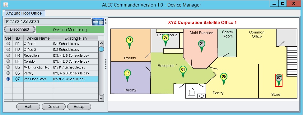
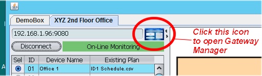
Alec Commander Pro makes managing multiple ZC001 devices incredibly easy! All you need is a JPG file of the layout of your office or factory and that can be immediately incorporated into the Alec Commander Device Manager screen. As can be seen in the above illustration, the devices are then defined and positioned on the layout corresponding to their actual location in the premises. This makes configuring and controlling any ZC001 extremely intuitive. All you need to do is to right-click on a device icon that represent that lighting zone and a menu will appear to let you config and control the device, program its schedule and read its energy consumption data. The followings describe the the few simple steps that you only need to create a comprehensive device layout map. Before we begin describing all the features in the Device Manager, please take note that if you need to open the Gateway Manager in order to make changes you can always click on the Gateway Manager Icon located in the red circled area of the Device Manager screen as shown below.
You should be able to use any graphic tools to convert your office layout plan into a good looking layout diagram and export the graphic into a JPG file for use by the Device Manager. We recommend keeping your JPG file resolution to no more than 1000 x 1000 pixels. The Device Manager will automatically scale the layout to fit into its layout window so super high resolution layout will still into the window but may slow down the program especially when multiple gateways are opened simultaneously.
When you first added a new gateway in the "Gateway Manager" you will be asked to provide the background layout diagram. If you have not yet prepared the layout JPG file you can select the "defaultLayout.jpg" as a starting point for experimentation and you can change the layout anytime later.
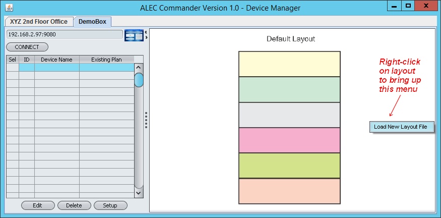
If you have now have a proper layout JPG file that you wish to use, you can right-click on the layout itself to bring up a "Load New Layout File" menu and it lets you change the layout. It is good to get your layout file ready before you define all the devices so that you don't have to re-position them later. For now lets just go with the defaultLayout.jpg file.
In our DemoBox example we have created a DemoBox Gateway and when you click the "OPEN" button on the Gateway Manager a device manager screen may looks like the following:
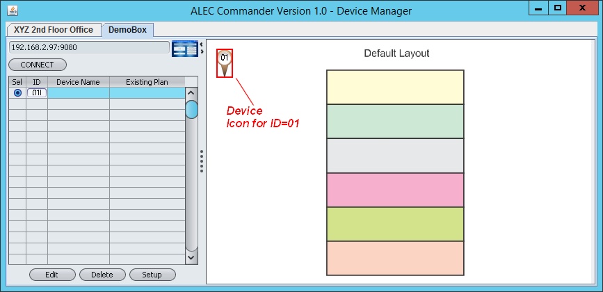
With a layout picture ready you can now add devices to the layout. What you do is to click on a cell in the "ID" column of the device table on the left hand pane and enter the ID of the device that have been assigned to the ZC001 that have been installed on your premises and networked to the gateway. The acceptable IDs are between 01 to FE (hexadecimal). The ID do not need to be consecutive so if you are not comfortable with using hexadecimal numbers for the ID, you can skip all the ID that can only be represented by hexadecimal notation and use only ID 01,02..09, 10, 11......99. This allow 99 devices to be networked to the gateway using what looks like a decimal number (the underlying ID are still hexadecimal, so ID 10 hex is really 16 decimal internally, but you don't have to worry about it).
However, if you are connecting more than 99 devices to the gateway (up to a maximum of 128 devices per gateway) then some of the devices will need to use the hexadecimal notations.
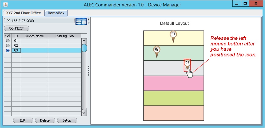
Once you have entered an ID a device icon will appear on the upper right corner of the layout pane as show below. The icon is light brown in color indicating that the Alec Commander is not connected to the Alec IoT Gateway and therefore no connection to the device icons.
To position the icon, simply click and hold your left mouse button for 1 second and the mouse pointer will change into a hand icon (
)you can then start to move the icon to the desired location on the layout background and release the mouse button when done. You may adjust the position of any device icon after you have placed them by left-clicking and holding on to the icon for 1 second until the mouse point change to a hand icon.
You can do this repeatedly for each ID until all the IDs have been defined and positioned.
This is all you need to do to setup your Device Manager! It is that simple.
For now you don't have to worry about the "Device Name" and "Existing Plan" columns on the device table. These will be filled automatically once Alec Commander Pro has connected to the gateway and these will be retrieved from each ZC001 and will be populated on the table automatically.
Saving Layout Design
At any time you can save your design to the Alec Configuration file by pressing the "Ctrl-S" key. This will bring up the File Saving dialog and you can save your design to the configuration file. The layout file location as well as the locations of all the device icons that you have just positioned will be saved to the file so that the next time you open up the gateway all of them will be in the correct place.
Zoom And Drag Background Layout
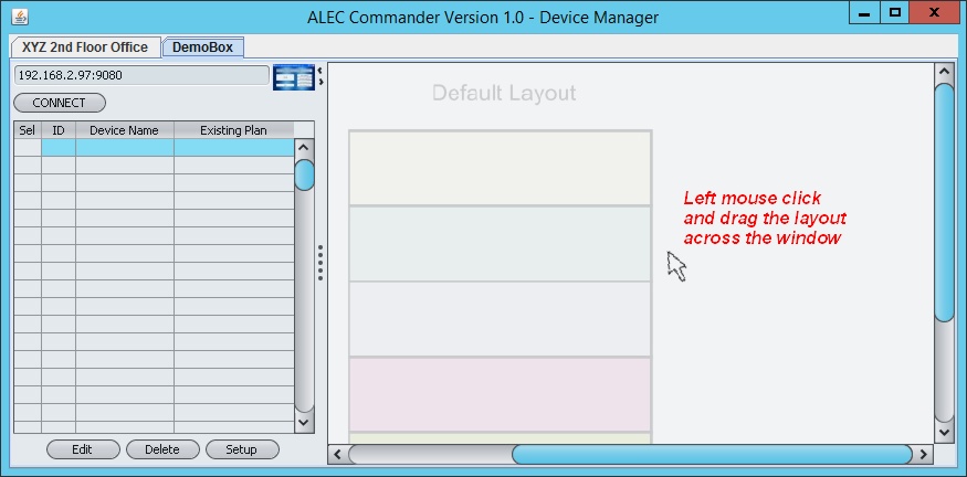
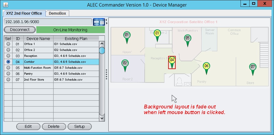
If you hold down the "Ctrl" key while turning the scrollwheel on your mouse you can zoom In and zoom out of the layout diagram. This can be useful if you have many devices on the same layout diagram that are crowded near each other and zooming in will let you see their detailed locations. Once you have zoomed in you can left-click on the layout diagram and drag it across its windows to see different part of the layout. Notice that when you left click on the layout the layout itself is fade out but all the device icons will remain visible. This also makes it simpler to identify where the lighting controllers are located if you have a very complex layout diagram.
If you left-click on the background layout the background will fade and help to expose the locations of the devices. You can left click and drag the background
If the Gateway is already connected to the LAN you can click the "Connect" button above the device ID table and Alec Commander will attempt to conenct to the Gateway immediately. If connection is successful Alec Commander will retrieved several data such as Device Name, existing lightning plan name etc from the connected devices and populate these data on the Device table.
The device Icon changes color to give you instant feedback on the state of each device
Not connected to the Gateway. Device ID01 is online and is OFF Device ID01 is online and is ON Device ID01 is online and is ON and is the currently selected device. Device ID08 is OFFLINE or Comm Error. If for any reason a device is uncontactable when the gateway tries to connect to it, its device Icon will be changed to a Red bubble as shown in the last row in the above table. It could be that the device ID has not been correctly set (default ID of ZC001 from factory are FF and they need to be changed to a unique ID before or after installation via the USB port) or it could be that the device has currently lost power.
When Alec Commander tries to contact a device, it will send a serial command over the RS485 network and wait about 0.5 seconds for a reply. If it receives no reply after the time-out it will try again and if it fail again then it will mark the device as error and a red icon will be used to represent the device that it could not contact. During the waiting time for a response that never comes, the software could not contact other devices that are active and therefore it would slow down the status updates of the other devices. For this reason, once Alec Commander mark a device as uncontactable it will skip contacting the same device for 100 cycles before it try to connect to the same device again. This is to speed up the status updates of only good devices.
If you observe that a device has been marked as OFFLINE but you believe that it is online you can force Alec Commander to test the communication with it again by clicking on the Red icon. Alec Commander will re-attempt to contact the device again and if it is successful it will take the device off the uncontactable list and will continue to update it status on the layout diagram.
Hence you should not add the ID of a non-existent device (perhaps a device you plan to install in future) to prevent Alec Command from trying to connect to it and slow down its performance. if a device is going to go offline for an extended period of time, it should be removed from the device table (using the "Delete" button on the bottom row of the device table pane). As you have seen It is very easy to add it back when the device is put back online again.
Retrieving Device Real-Time Data
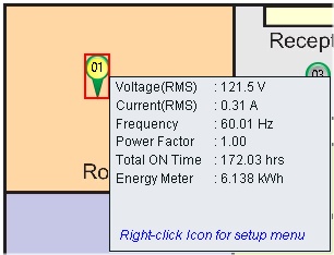
When you use the left mouse button to click on a device Icon that is online it will query the device and retrieve its real time data. The data will be displayed on a popup "Info Window". As there are more data to display than could comfortably fit on a single "Info Window" the data are presented in two separate screens. You can toggle between the two screens by left-clicking on the popup box. The popup box will close automatically after a few seconds unless you continue to move your mouse within it to keep it open. Example of Info Window displays are as follow:
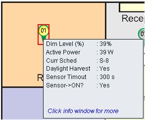
Most items are self explanatory.
DIM Level: This is the control dimming output level from ZC001 to the the lighting fixture. It is usually either set by the program schedule or it is the last user-set light level when a light is turned ON. When daylight harvesting function is enabled, ZC001 will start off its DIM level determined by the program or user. But once daylight harvesting function kicks in the controller will adjust the dimming output gradually until the actual brightness its lux meter see matches the desired brightness level.
Total ON Time ZC001 maintain a counter to log the cumulative number of minutes that the lights has been turned ON. The ON time does not take into account the dimming level of the light, it only count the time when the light power has been turned ON by its relay. When the lights is turned OFF (power cut) by ZC001 the counter would stop accumulating the time. Energy Meter This logs the total amount of energy in Kwh that has been consumed by all the lights that are powered by this particular ZC001 device. By dividing the Energy Meter reading by the Total On Time you can obtain an the average power the lighting fixtures consumes and that could be a useful matrix to estimate the life span of the lighting fixtures.
You can choose to setup and control the device by first selecting it on the layout map or on the device table, then click on the "Setup" button.
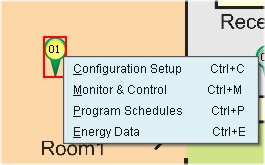
A more intuitive method is to use the right mouse button to click on the device icon that you want to setup. A menu will popup as shown below:
4 commands are available and each will be described in its own help file page:
4) Energy Data