i-TRiLOGI Ladder Logic Editor

    The Circuit Editing Mode

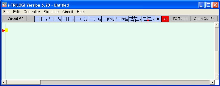
i-TRiLOGI comes with a smart editor which allows you to insert or delete a single element within a circuit easily. The editor interprets your circuit immediately upon entry and prevents you from creating illegal circuit connections. The functions of various keys in the circuit editing mode are detailed below. You know that you are in the circuit editing mode when a row of ladder logic icons appears along the upper status line next to the circuit number and a yellow color highlight bar appears and you can move it  to select an element in the ladder circuit, as shown below:

editla3.jpg (35044 bytes)

Mouse Actions

Left Click - When you click on an element using a the left mouse button, the element is selected and   highlighted by the yellow color highlight bar.

Right Click - When you click on an element using the right mouse button, you are allowed to directly edit the label name of the element. This can be a convenient feature if you need to change one or two characters in the name only. However, if the element is a custom function [dCusFn], or [CusFn], then the custom function editor will be opened for you to edit the function directly.

Insert Ladder Element - You create the ladder circuit element simply by moving the mouse pointer to the icon and pressing either the left or the right mouse button to insert a ladder logic element to the currently highted element. The following is a description of the functions of each icon. A yellow color highlight bar will appear which you can move to select an element in the ladder circuit.

tutorial1c3.gif (330 bytes)

<1> - Left click to insert a normally-open series contact. 
<2> - Right click to insert a normally-closed series contact.
tutorial1c4.gif (215 bytes) <3> - Left click to insert a N.O. parallel contact to highlighted element
<4> - Right click to insert a N.C. parallel contact to highlighted element
tutorial1c5.gif (209 bytes) <5> - Left click to insert a N.O. parallel contact to enclose one or more elements.
<6> - Right click to insert a N.C. parallel contact to enclose one or more elements.
tutorial1c6.gif (197 bytes) <7> - Insert a normal coil which may be an output, relay, timer or counter.
tutorial1c7.gif (209 bytes) <8> - Insert a parallel output coil (not an entire branch) to the current coil.
tutorial1c8.gif (219 bytes) <9> - Insert a special function coil which includes execution of CusFn
tutorial1c9.gif (223 bytes) <0> - Insert a parallel special function coil to the current coil.
tutorial1c10.gif (216 bytes) </> -  Invert the element from N.O. to N.C. or from N.C. to N.O.
contac9.jpg (1489 bytes) <^> -  Convert the element to a rising-edge triggered contact (one shot)
tutorial1c11.gif (145 bytes) Click to move the highlight bar to the right (same effect as pressing the right arrow key). This can be used to move the cursor to a junction which cannot be selected by mouse click.
tutorial1c12.gif (153 bytes) Double-click to delete a highlighted element. This acts as a safety against mistake.


When you click on an icon, for example, the tutorial1c3.gif (330 bytes) . The icon will change to bright yellow color to show you the element type that you are creating. At the same time, an I/O table should appear on the screen with a light beige-color background. The I/O table acts like a pop-up menu for you to pick any of the pre-defined label name for this contact. This saves you a lot of typing and at the same time eliminates typo errors that could result in a compilation failure. You should spend a few minutes to follow the "Ladder Logic Programming Tutorial" on the steps needed to create a ladder program.

As mentioned previously, the ladder editor is intelligent and will only accept an action that can result in the creation of a correct ladder element. Otherwise it will simply beep and ignore the command.


UNDO Circuit Editing

If you have wrongly inserted or deleted an element and wish to undo the mistake, you can either select "Undo" from the "Edit" menu or press <Ctrl-Z> key to undo the last step. The undo buffer stores the last 10 editing steps. You can also choose to abort all the operations on the current circuit by selecting "Abort Edit Circuit" to abort all changes made to the current circuit.

Create Ladder Circuit Using The Keyboard

Users of existing i-TRiLOGI version 3.x or 4.x who are familiar with creating ladder programs using the keyboard will be delighted to know that they can still create their ladder programs using the keyboard.  The keyboard actions are described below:

Left/Right/Up/Down cursor keys

The cursor keys are for moving the  highlight bar from one element to another in their four respective directions. You can only move in a direction which will end up with an element.

<ESC>

Press <ESC> key to end the circuit editing mode and return to the browse mode of the logic editor.

<Enter>

When you are done with editing the current circuit, hit <Enter> to proceed to the next circuit.

<SHIFT> or <TAB>

If you observe the highlight bar carefully, you will notice a dark green color square at the right end of the highlight. This indicates the insertion location where a series contact will be attached. You can change the insertion location to the left  or the right of the highlight bar by pressing the <SHIFT> key. 

Note: From version 5.32 onwards,   the <SHIFT> key is now being used for this action instead of <TAB> key because the <TAB> key no longer works under Java JRE 1.4.x and up. However, for user of JRE 1.3.1, either <SHIFT> or <TAB> keys will work.

The position of the cursor has no effect when you connect a parallel contact to the highlighted element. The left terminal of the element will always be connected to the left side of the parallel branch.

<0> to <9> , </> & <E> keys

Pressing the key <0> to <9> and </>  is equivalent to clicking on the icon shown in the table. The equivalent keyboard number is shown as a small numeral at the lower right corner of the icon. The </> key is the quickest way of converting a normally-open contact to a normally-closed one (and vice versa).

Pressing the <E> key when a contact or coil is selected allows you to edit the label name directly. Note that it is the user's responsibility to ensure that the label is valid.