PB01-BWS-2
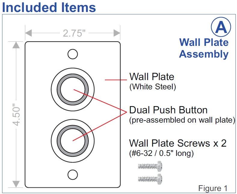
Dual Push Button Switches on White Steel Plate
Description
Description
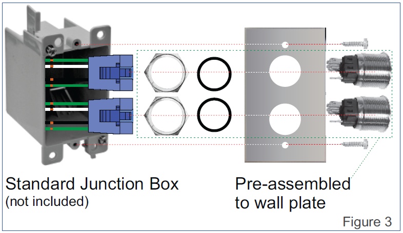
The PB01-BWS-2 contains two push button switches, each with a 12V blue-color LED ring around the switch. The two switches are meant to connect to two Alec Zone Controllers ZC001, where each ZC001 will control its own zone of lighting fixtures. The switches are pre-assembled onto a single-gang, US-style white steel wall plate with 2 holes. Two quick-connect sockets are included in the package to enable simple wiring.
The push buttons are UL-approved and are capable of switching loads of up to 250VAC @5A. However, when used with the Alec-ZC001 the switches are only working at 12VDC and only conduct current < 5mA.
The LED ring light operates at 12VDC (extra low voltage) and draws < 20mA of current each when fully lit. ZC001 is able to control the brightness of the LED ring light and use it to provide both for illumination in the dark as well as serving as a status indicator to inform the user of the operating state of the ZC001. (For example if the LED is blinking rapidly and continuously it indicates an overcurrent circuit breaker has been triggered.)
An overview of the wall plate, button, and wire socket assembly is shown in figure 3.
Installation Instructions
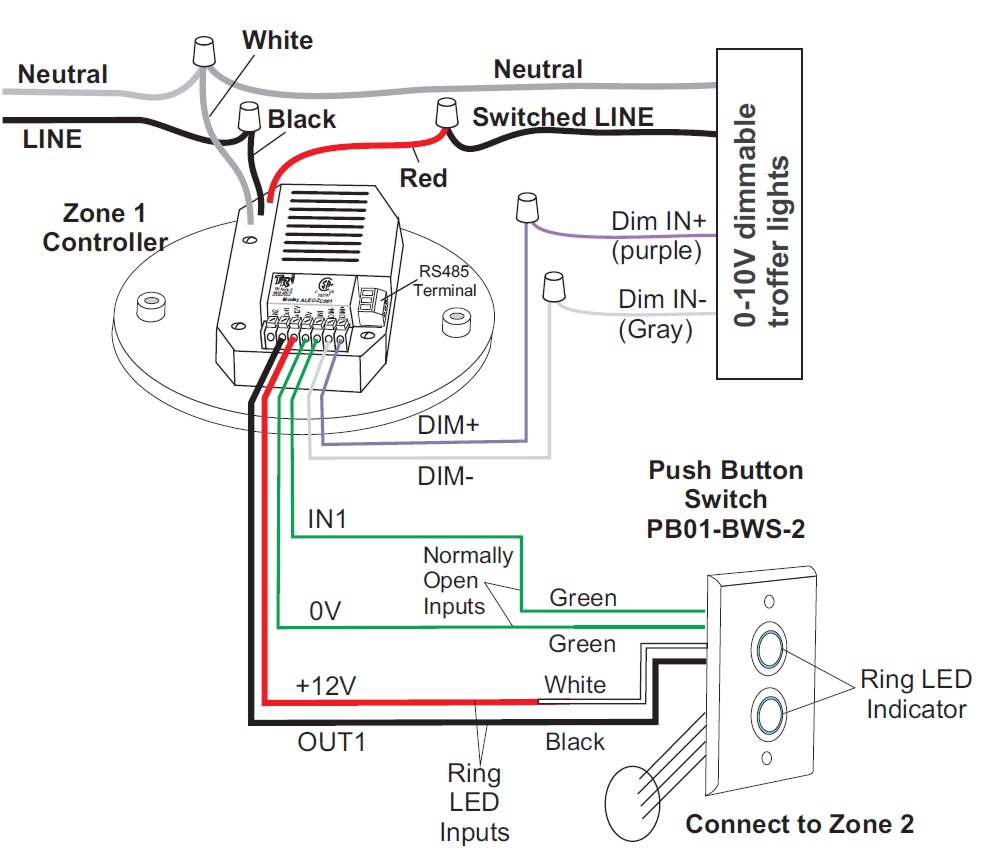
The PB01-BWS-2 is normally mounted to the wall (same position as a normal light switch) and low voltage cables* with at least 4 wires (e.g. CAT-5 cable) can be used to connect each push button switch on the PB01-BWS-2 to the corresponding ZC001.
Two of the wires connect to the Normally-Open contacts on the push button switch and the other two wires connect to the LED ring indicator terminals.
* May require plenum grade cable when run in the plenum space.
As the ZC001 is normally mounted on the ceiling, the installer may need to run the low voltage cable inside the wall and bring it to the ceiling.
Since only low voltage (12VDC) and low current (< 25mA) are used between the PB01-BWS-2 switches and the ZC001, it is not necessary to install the standard wall switch junction box before you can install the PB01-BWS-2. For new installation you could simply cut a retangular hole large enough to accomondate the two switches on the partition wall and mount the wall plate directly onto the wall.
For retro-fit installation you could install the PB01-BWS-2 onto existing light switch junction box after removing the existing switch and shorting the old switch terminals so that main power can be brought to the ZC001 on the ceiling.
Wiring Instructions
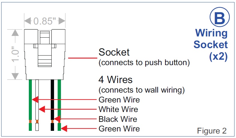
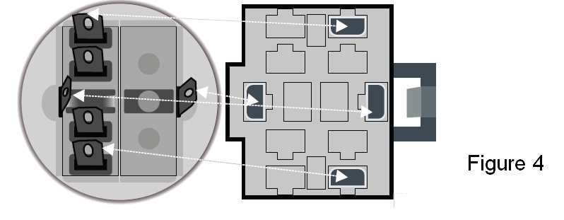
First, connect the wiring socket (B)-Figure 2 to the push button switch (A)-Figure 1. Please Ensure the 4 outer prongs of the switch are inserted correctly to the contact pins on the sockets. Rotate 180º if it is not correctly aligned.(See Figure 4)
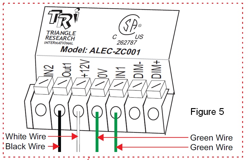
- Connect: Black wire to Out1 wire on ZC001
- Connect: White wire to +12V wire on ZC001
- Connect: one of the Green wires to 0V wire on the ZC001
- Connect: the second Green wires to IN1 wire on the ZC001
Please refer to Figure 5 for details.