MoSen-LR Installation Guide
Supplementary Motion Sensor (Long Range) For Alec Zone Controller
After you have unpacked the MoSen-LR you should see the items as shown in Figure 1. Measuring only 3cm(L) x 3cm (W) x 1.25cm(H) (1.2"x1.2"x0.5"), a MoSen-LR sensor occupies very little space and is barely noticeable after it has been installed.
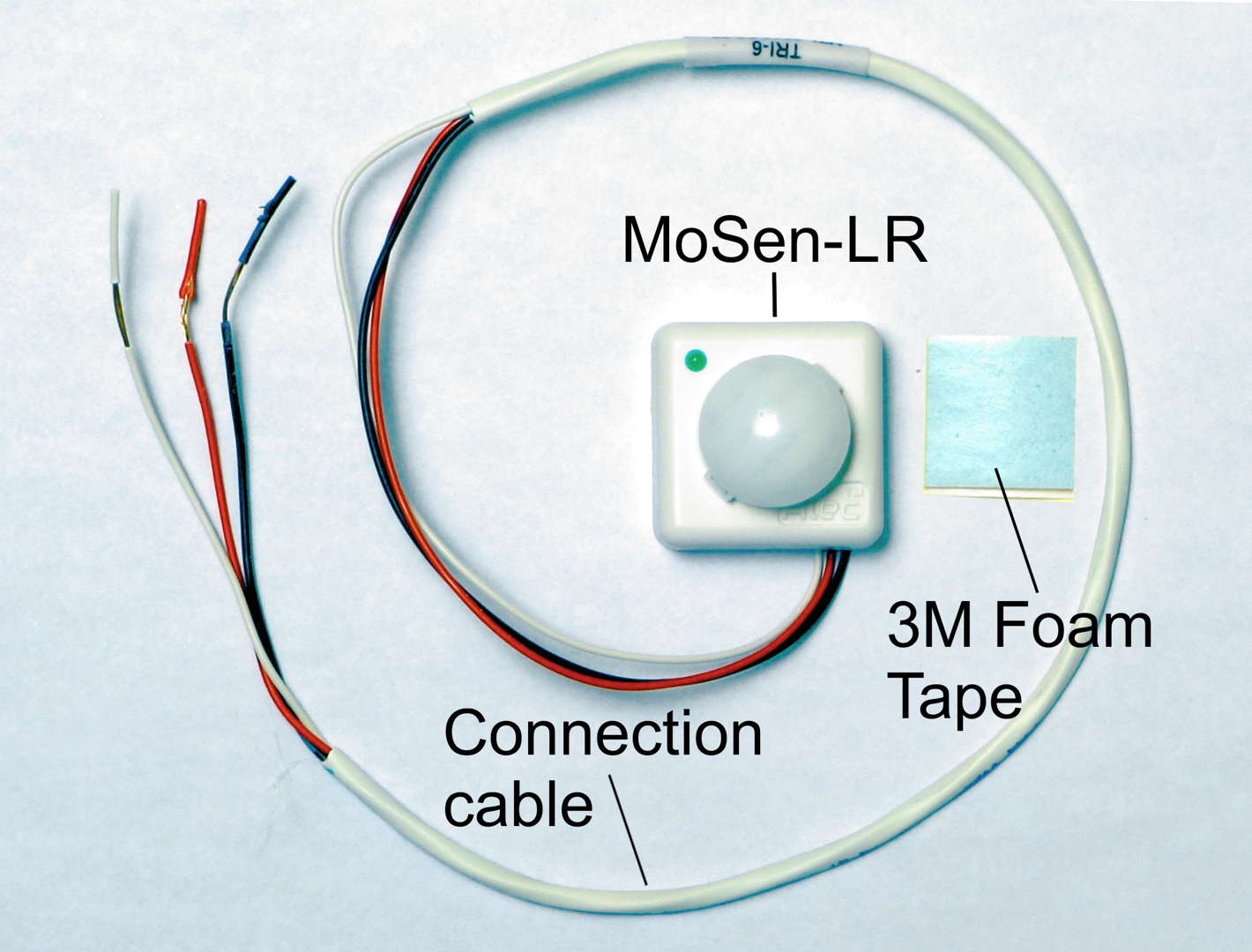
Figure 1
MoSen-LR is supplied with a short connection cable so the installer will need to extend the cable using low voltage cable of appropriate length to connect from a MoSen-LR to the Alec Zone Controller (ZC001/ZC002). We recommend using a low voltage cable with Red, Black and a third color for consistency. However, if you choose to use a CAT-5 cable as extension then we recommend using the following CAT-5 color codes to extend the cable:
| MoSen-LR | CAT-5/5e/6 |
| RED (V+) | Orange |
| Black (0V) | Blue |
| White (signal) | White/green |
Description
The MoSen-LR is an optional, supplementary long range motion sensor that can be used to extend the sensing range of the built-in motion sensor on Alec ZC001/ZC002 for applications where the lighting controller need to be installed on a high ceiling > 15 ft and as high as 40 ft.
The Alec ZC001 and ZC002's built-in motion sensor has a maximum detection range of 16.5 ft (5m),
which may not be able to detect occupancy when it is installed on very high ceiling > 15 ft such
as high bay lightings used in warehouses. In such applications the MoSen-LR can be used to provide occupancy sensing
by connecting to the Alec ZC001/ZC002's auxiliary sensor input (IN2).
The motion sensor on the MoSen-LR has a maximum linear detection distance of 40 ft (12m). It also has a field of view angle of 45o from the center line. So if the ceiling height is h and h < hmax, then the horizontal limit r of the built-in motion sensor from the center line is r = h*tan(45o) = h and the coverage area = π*r2 as shown in the following diagram:
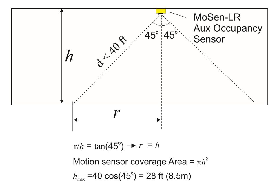
Figure 2
E.g. if h = 24 ft, r = 24 ft then the sensor covers a circular area of about 1800 ft2 around the ZC001/ZC002.
if h > hmax then the detection angle will be narrower due to the maximum of 40ft
linear limit.
The following table gives you a quick reference of the
coverage area of the Alec-ZC001 / ZC002 for different ceiling heights.
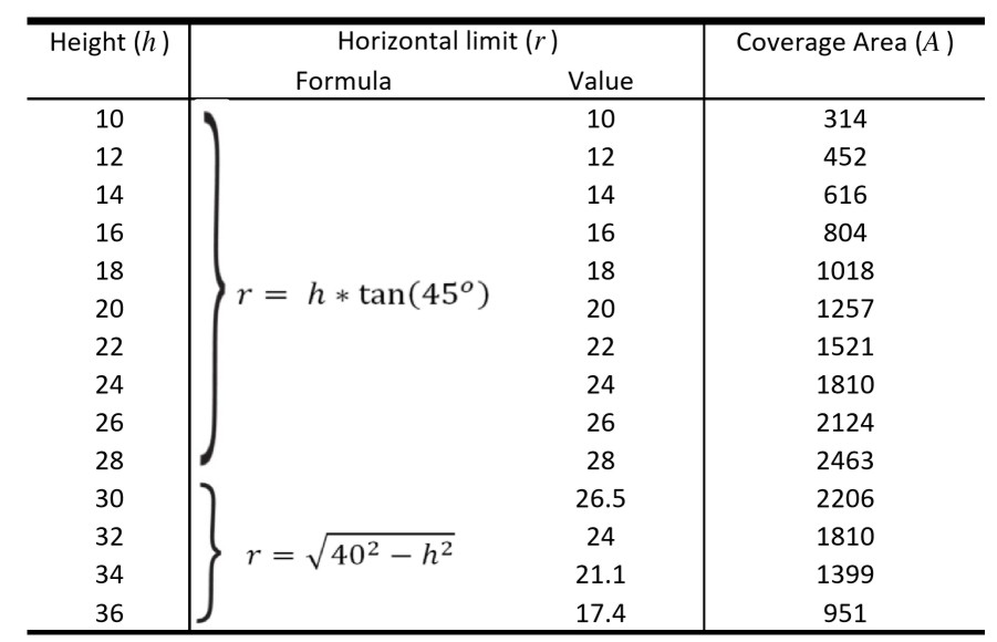
Figure 3
Notes:
- As many MoSen-LR as needed can be wired in parallel to an Alec-ZC001/ZC002 controller, offering excellent flexibility in how you may want to configure the zones to maximize energy saving or to minimizing costs.
- MoSen-LR can be added anytime, even after a project has already been installed and is in operation.
- If you need to install sensors on a ceiling that is lower than 12 ft then you should consider using the MoSen-SR (SR stands for "Standard Range") which is designed for office or residential lightings and is more suitable for low ceiling height applications.
Installation Instructions
A MoSen-LR has an attached cable with 3 wires. The installer can extend the wire using any low voltage cable such
as the thermostat or alarm wires, or even CAT-5 cable.
A piece of 1" x 1" square, 3M double-sided foam tape is included in the package that allows the small
and light-weight MoSen-LR to be easily adhered to any solid surface on the ceiling. First, peel the backing paper
of the foam tape and paste the foam tape onto the back of the MoSen-LR. When you have selected the position to install the
MoSen-LR, remove the other backing paper of the foam tape and press the MoSen-LR onto the location you want
to install it.
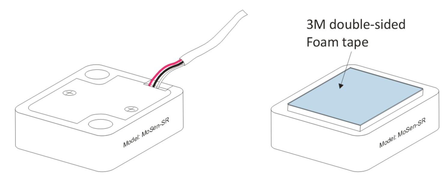
Figure 4
Wiring Instructions
There are 3 wires on the MoSen-LR - Red (V+), Black (0V) and White (signal).
MoSen-LR can be powered by 5V to 15VDC applied to the red (V+) and black (0V) wires.
The white wire is the signal output from MoSen and together with the black wire it forms
an active low input to be connected to the Alec ZC001/ZC002 auxiliary sensor input (IN2) to
provide additional occupancy sensing signals.
As each MoSen-LR consumes < 5mA when activated, it can be powered directly from the 12V and 0V terminal on the low voltage control I/O terminal on the Alec ZC001 as shown in Figure 6 (A).
- Connect: Red wire to +12V wire on ZC001
- Connect: Black wire to 0V wire on ZC001
- Connect: White wire to IN2 wire on ZC001

You can connect as many MoSen-LR that is needed to a single ZC001 or ZC002 controller.
The output signal wires (white & black) of all the MoSen-LR will be connected in parallel to the
zone controller.
Note that If you are connecting more than 4 MoSen-LR to a single ZC001/ZC002, then you should use an external 5V to 15V DC power supply module to supply power to all the MoSen-LR. In this case the black wires of all the MoSen-LR will need to be connected both to the external power supply as well as the 0V terminal on the Alec ZC001/ZC002, as shown on Figure 6(B).
Operating Instructions
When a MoSen-LR detected motion (occupancy) it's signal output (white wire) will alert the AlecZC001 that occupants have been detected and to take action according to the program schedule.
There is a green LED indicator on each MoSen-LR and it will light up only when it has detected motion. Note that the MoSen-LR was designed so that the green LED indicator is not affected by the active signal outputs from the other MoSen-LR that may be wired in parallel. Meaning, each MoSen-LR will only indicate detection by its own sensor. However, the Alec controller will not be able to determine the particular MoSen-LR that detected motion, only that motion was detected within the zone.