Alec GW-E01 Installation Guide
Unpacking Alec IoT Gateway model: GW-E01
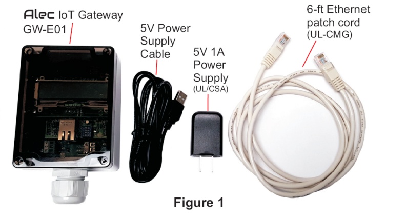
The Alec IoT Gateway model: GW-E01 box contains the GW-E01 module, a 5V,
1A power supply and a power supply cable, as well as a 6-ft long CAT-5
Ethernet patch cord for connecting the gateway to the Local Area Network.
The GW-E01 module is housed inside an industrial grade NEMA4/IP66, UL508-
approved plastic enclosure and has a smoke color polycarbonate lid. The lid is
not screwed on when shipped and a packet of screws are included inside the
box so that the user may screw on the lid after wiring.
A cable grip is provided that allows external wiring into various wiring points
on the GW-E01 main circuit board as described in the following sections.
Select The Installation Location For Alec GW-E01
it should be installed at a location where it is close to an Ethernet point and a power outlet. The RS485 network that links all the ZC001 obviously also needs to be brought to the location where you want to install the GW-E01. Note that electrically speaking, the GW-E01 is a node just like any of the ZC001 nodes that are connected to the multi-drop RS485 network. Therefore the GW-E01 can be installed anywhere along the RS485 daisy-chained bus and DOES NOT need to be positioned only at either end of the RS485 network.
Wiring Alec GW-E01
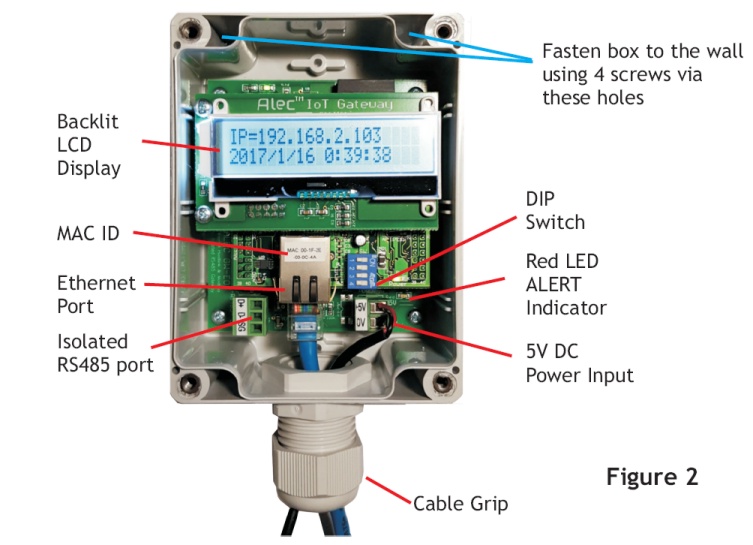
First, remove the lid of the GW-E01 box to see the various wiring points on a
GW-E01. Turn the knob on the cable grip counter-clockwise to loosen the
gripping rubber and then insert 3 sets of cables into the housing to connect to
the following wiring points:
- At the center is the Ethernet RJ45 connector. Due to the size of the RJ45 plug this should be the first connector threaded through the cable grip.
- To the left of the Ethernet connector is a 3-position detachable screw terminals with the markings of "D+, D- and SG". This is an isolated RS485 port where D+ and D- connect to the multi-drop RS485 signals and SG is the "signal ground" that provides a common reference ground for all the connected Alec-ZC001.
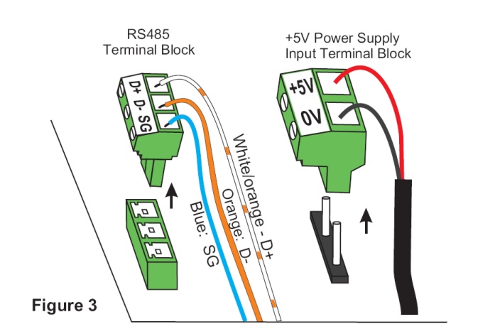
To connect wires to the screw terminals, first grab the body of the terminal block and pull it up vertically. Once it has been detached from the terminal holder, insert the 3 x RS485 wires to the terminal as shown in Figure 3 and then tighten the fastening screw using a small screw driver.
- At the lower right end of the GW-E01 main board, there is a 2-position screw terminal block marked with "+5V" and "0V". Remove the terminal block from its two-pin header by grabbing it and pulling it up vertically. Then, connect the red wire of the power supply cable to the "+5V" terminal, and the black wire to the "0V" terminal. Tighten the screw using a small screw driver and then insert the terminal block back onto the header pins as shown in Figure 3.
After all 3 sets of wiring has been completed, tighten the cable grip by rotating the knob clockwise until all the cables are tightly gripped. This should provide good protection for regular usage in commercial and industrial environment. However, note that the cable grip entrance into the enclosure is not fully waterproof, unless special sealing rubber or sealing compound is applied to seal up any air gaps between the cables.
RS485 Wiring Notes: Termination and Biasing
- Since both ZC001 and GW-E01 employ isolated, Fail-safe class of RS485 drivers, the RS485 bus does not require biasing resistors for stable operation.
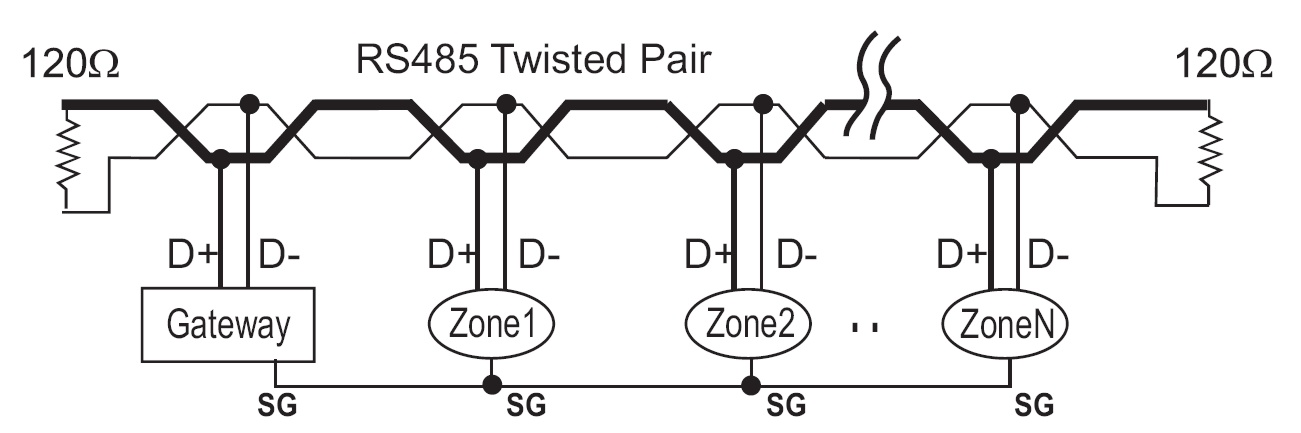
- The RS485 standard specifies impedance-matching termination at both ends
of the daisy-chain RS485 network. Unfortunately, termination also increases
the current consumption of the RS485 driver. Since the Alec RS485 network
operates at a relatively slow speed of 38400bps, our calculations show
that it is possible to operate well at up to 300m (1000 ft) without
connecting terminating resistors.
However, if the RS485 cable-run between the first and the last device in the network exceeds 300m (1000 ft), then you should add a 120 ohm resistor across the D+ and D- terminal at the last two 'corners' of the bus. This will allow the total cable-run to extend up to 1200m (4000 ft).
Using Alec GW-E01
After the wiring of the GW-E01 is completed, you may plug the power supply
module to the power outlet to turn on power to the GW-E01. If properly wired,
the LCD display should light up. By default, the GW-E01 is configured to
request for an IP address from the network DHCP server. GW-E01 will wait up
to 10 seconds for the IP address from the DHCP server. The IP address will be
displayed on the first line of the LCD display as shown in Figure 5. You
will need this IP address to access and setup the GW-E01 using the Alec Commander Pro software

If GW-E01 fails to receive the IP address from the LAN after 10 seconds, it will
display "IP = 0.0.0.0". You will need to check if the Ethernet point it connects
to is a working network point. If so, power cycle the GW-01 and try again.
Once you have obtained the IP address, you should submit a request to your SysAdmin to
to reserve the IP address for this device's MACID (the MACID
is shown on the Etherner connector on the GW-E10 - See Figure 2).
Alternatively, you can also use the Connect & Configure function on the Alec Commander Pro software
to set a static IP address for GW-E01, so that every
time it will start up to the same IP address.
Alec GW-E01 Real Time Clock
The GW-E01 has a built-in Real Time Clock (RTC) and it displays its RTC data (i.e.
the current date and time) on the 2nd line of the LCD display.
The RTC data on the gateway is very important as every minute the gateway will broadcasts
its RTC data to all the ZC001 that are connected to its RS485 port. This means that there
is no need to set the clock for each individual ZC001 on your installation (in large installation
it could be hundreds or even thousands of zones). It also ensures that all the ZC001s'
RTC are synchronized to the same time so that the scheduling functions can operate accurately.
The RTC on GW-E01 is battery-backed so it only needs to be set once and will continue
to keep time even when the power is lost. However, as with any stand alone, crystal-controlled
clock the RTC will experience some drift after running for some months or years.
Fortunately, since the Gateway is to be connected to the LAN, it is capable of
updating its RTC by getting the more accurate RTC data from a server on the Internet.
Hence if you enable it to auto-update its RTC once a day from the Internet then
the gateway will always keep very accurate time and it will also make sure that
all the connected zone controllers are updated to the same time.
GW-E01 can also be configured to automatically adjust its daylight saving time at the
moment when the time change take place, and also update all the ZC001 to the same new time
settings.
The GW-E01 RTC configuration settings is also performed using the Alec Commander Pro
Connect & Configure function. Please refer to Alec Commander Pro
software help files for details.
GW-E01 Specifications
| Item | Description |
| Power Supply | DC5V, 0.5A |
| Ethernet Connection | RJ45 Socket, 100Mbps |
| RS485 Port | Isolated, 38400bps, Fail-Safe Transceiver |
| Dimensions | 6"(L*) x 3.5"(W) x 2.5"(D) *Length includes cable gland |
| Weight | 12 oz (0.35kg) |